- HOME
- 產品介紹
- 半導體事業部
- Hamamatsu Photonics
- Mass spectrometry
- MCP(Microchannel Plate)
MCP(Microchannel Plate)
![]() +886-2-8772-8910
+886-2-8772-8910
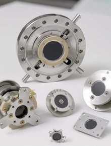
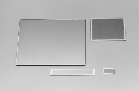
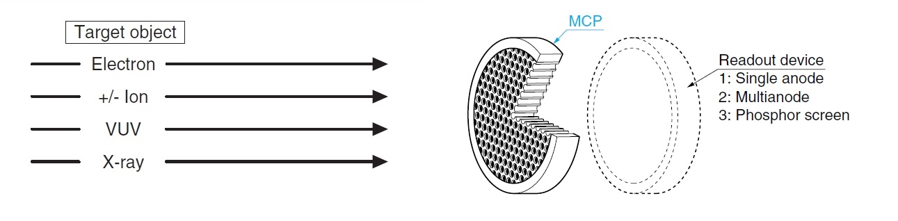
MCP(微通道板)是偵測在真空中的電子,離子,真空紫外光,X射線和γ射線,並放大檢測到的信號的二維傳感器。Hamamatsu 提供各種尺寸的圓形及方型的MCP(微通道板),包含易於安裝的MCP模組。這些MCP廣泛應用於許多類型的分析設備,如“質譜分析”,“半導體檢測”和“表面分析”。
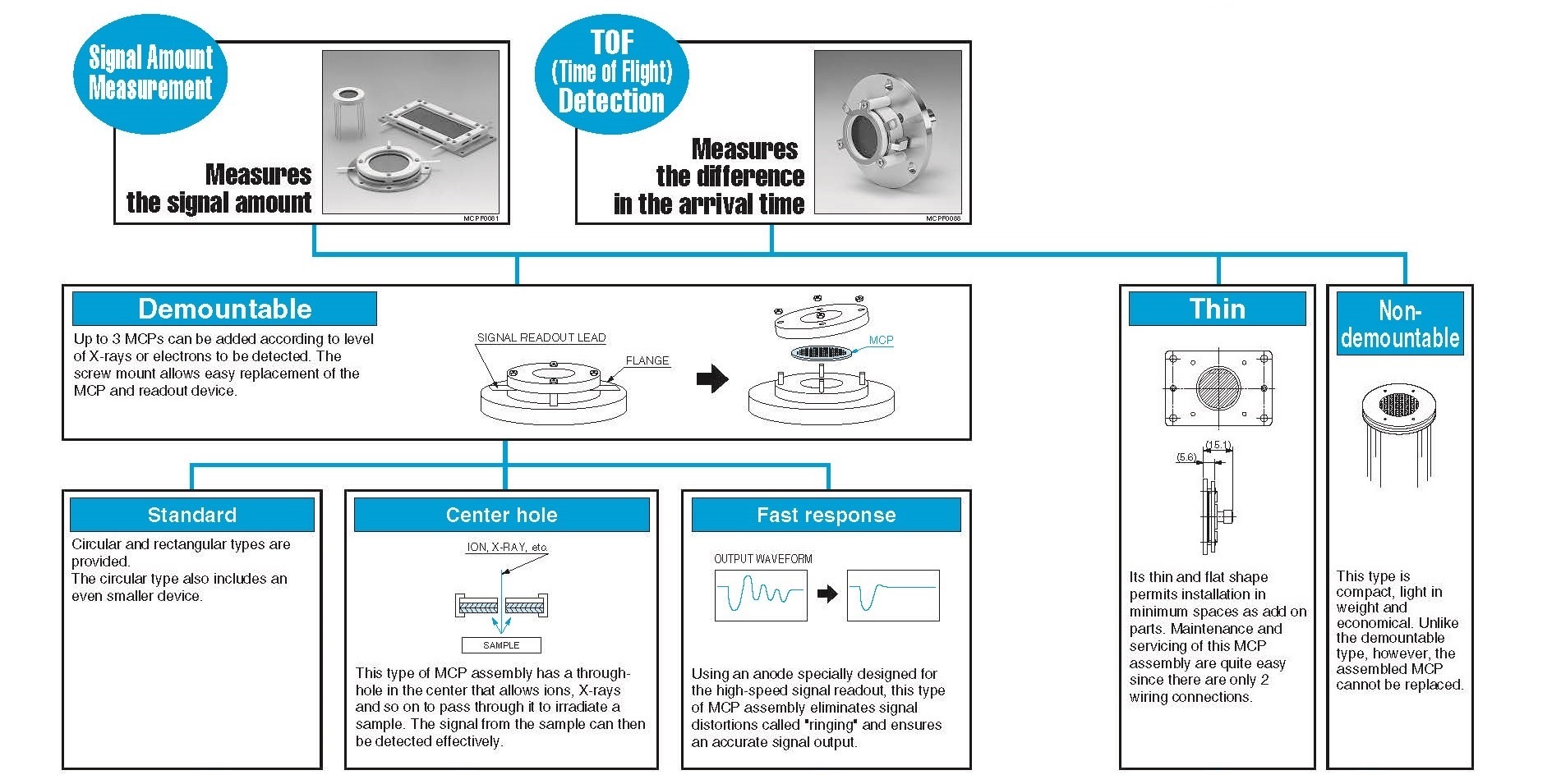
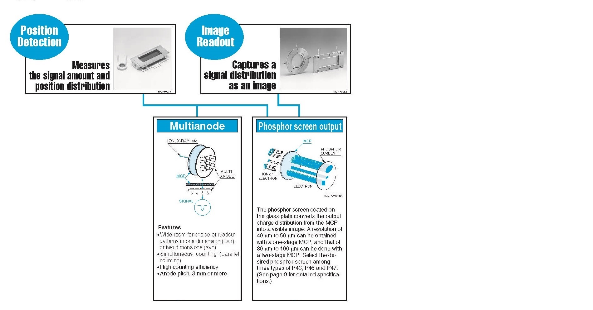
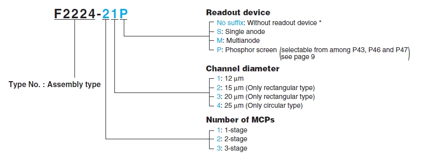
MCP組件提供三種不同的讀取裝置,以滿足應用需求;分別為器件有:(1)單陽極(有效區域內的電輸出信號測量),(2)多節點(與信號輸入位置對應的電氣輸出信號測量)和(3)熒光屏(輸出信號的光學成像)。
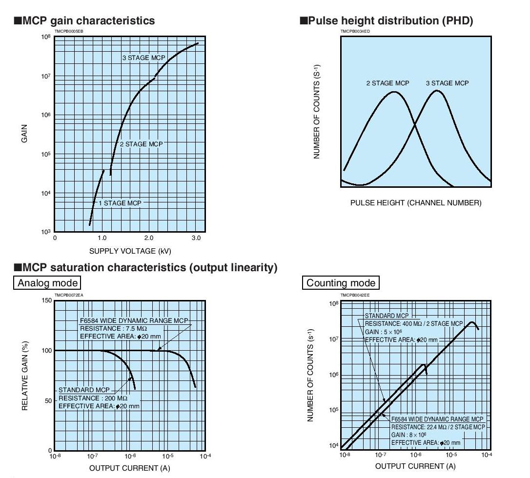
As shown in the figure on the lower right, a potential gradient is established along the channel when the voltage VD is applied be- tween the input and output sides of the MCP. Multiple secondary electrons are emitted when an electron enters a channel from the input side and strikes its inner wall. These secondary electrons are accelerated by the potential gradient to draw parabolic trajecto- ries that are determined by their initial velocities. They then strike the opposite wall in the channel causing further secondary elec- trons to be emitted. The electrons in this way travel towards the output end while striking the inner wall of the channel repeatedly. As a result, a large number of exponentially increased electrons are extracted from the output side.
|
■Thickness
The thickness of an MCP is nearly equal to the channel length. The ratio of the channel length (L) to the channel diameter (d) is referred to as α (α=L/d), and this α and the secondary emission factor inherent to the channel wall material determine the gain of the MCP. Standard MCPs are fabricated so that α is 40 to 60. The MCP thickness is therefore determined by the required chan- nel diameter and the design value of this α.
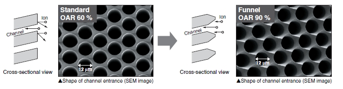
■Open Area Ratio: OAR
The OAR indicates the ratio of the channel open area to the en- tire effective area of and MCP.
■Bias angle
The bias angle is an angle formed by the channel axis and the axis perpendicular to the plate surface. This angle is chosen by considering the detection efficiency and spatial resolution as well as the prevention of input signals from passing through the channels without colliding with the channel walls. The optimum value is usually from 5° to 15°.
|
 |
The open area ratio (OAR) of standard MCPs (microchannel plate) is normally set to about 60 %, but we also provide "funnel type" MCPs (microchannel plate) whose open area ratio is improved up to 90% in order to guide more signals into each channel. Please contact us if you are interested in funnel type MCPs (microchannel plate).
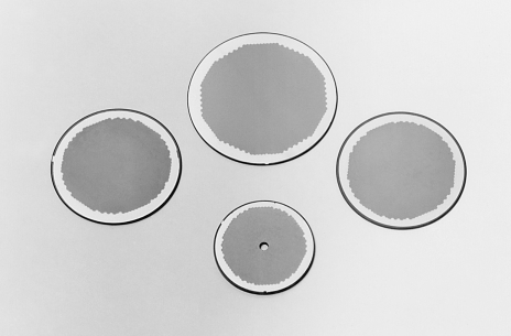
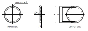
◎ Circular MCP
|
Type |
F1551 |
F1094 |
F1552 |
F1208-01 |
F1217 |
F1942-04 |
F2395-04 |
Unit |
||||||||
|
-01⑤ |
-06 |
-011 |
-074 |
-01⑤ |
-011 |
-074 |
-01⑤ |
-011 |
-074 |
-01⑤ |
-011 |
|||||
|
Outer size A |
17.9 |
24.8 |
32.8 |
38.4 |
49.9 |
86.7 |
113.9 |
mm |
||||||||
|
Electrode area B |
17 |
23.9 |
31.8 |
36.5 |
49 |
84.7 |
112 |
mm |
||||||||
|
Effective area C |
14.5 |
20 |
27 |
32 |
42 |
77 |
105 |
mm |
||||||||
|
Thickness D |
0.48 |
0.2 |
0.48 |
0.3 |
0.48 |
0.3 |
0.48 |
0.3 |
0.48 |
0.48 |
1 |
mm |
||||
|
Channel diameter |
12 |
4 |
12 |
6 |
12 |
6 |
12 |
6 |
12 |
12 |
25 |
µm |
||||
|
Channel pitch |
15 |
5 |
15 |
7.5 |
15 |
7.5 |
15 |
7.5 |
15 |
15 |
31 |
µm |
||||
|
Bias angle θ |
8 |
12 |
8 |
12 |
8 |
12 |
8 |
8 |
12 |
8 |
degrees |
|||||
|
Open area ratio |
60 |
55 |
60 |
% |
||||||||||||
|
Electrode material |
Inconel |
— |
||||||||||||||
|
Gain (Min.) ③ |
104 |
5×10³ |
104 |
5×10³ |
104 |
5×10³ |
104 |
— |
||||||||
|
Resistance ③ |
100 to 700 |
10 to 100 |
20 to 100 |
20 to 200 |
50 to 500 |
10 to 50 |
10 to 100 |
15 to 200 |
6.7 to 33.3 |
6.7 to 66 |
20 to 100 |
10 to 200 |
4 to 20 |
10 to 100 |
5 to 50 |
MΩ |
|
Dark current (Max.) ③ |
0.5 |
pA·cm-2 |
||||||||||||||
|
Maximum linear output ③ |
7 % of strip current ② |
— |
||||||||||||||
|
Supply voltage ④ |
1 |
kV |
||||||||||||||
|
Operating ambient temperature ④ |
-50 to +70 |
°C |
||||||||||||||
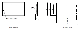
◎ Rectangular MCP
|
Type |
F2370-01 |
F4772-01 |
F2806-01 |
F1943-02 |
F2805-03 |
F2396-04 |
Unit |
|
Outer size A×A' |
15.9×9.4 |
61.9×13.9 |
49.9×39.9 |
87.9×37.9 |
59.9×59.9 |
96.9×78.9 |
mm |
|
Electrode size B×B' |
15×8.5 |
61×13 |
49×39 |
87×37 |
58×58 |
95.6×77.3 |
mm |
|
Effective area C×C' |
13×6.5 |
55×8 |
45×35 |
81×31 |
53×53 |
90×72 |
mm |
|
Thickness D |
0.48 |
0.6 |
0.8 |
1 |
mm |
||
|
Channel diameter |
12 |
15 |
20 |
25 |
µm |
||
|
Channel pitch |
15 |
19 |
25 |
31 |
µm |
||
|
Bias angle θ |
8 |
degrees |
|||||
|
Open area ratio |
60 |
% |
|||||
|
Electrode material |
Inconel |
— |
|||||
|
Gain (Min.)③ |
104 |
— |
|||||
|
Resistance③ |
100 to 500 |
20 to 200 |
20 to 120 |
10 to 50 |
MΩ |
||
|
Dark current (Max.)③ |
0.5 |
pA·cm-2 |
|||||
|
Maximum linear output③ |
7 % of strip current② |
— |
|||||
|
Supply voltage④ |
1 |
kV |
|||||
|
Operating ambient temperature④ |
-50 to +70 |
°C |
|||||
◎ Circular (Non-demountable)
|
Anode type |
Number of MCPs |
|---|---|
|
Without readout device |
1 to 3 |
|
Single anode |
|
|
Multianode |
Phosphor output type are not available.
|
Symbol |
Description |
F1551 |
F1094 |
F1552 |
F1208 |
F1217 |
Unit |
||
|---|---|---|---|---|---|---|---|---|---|
|
A |
Assembly outer size |
φ27 |
φ34 |
φ42 |
φ49 |
φ62 |
mm |
||
|
B |
Effective area |
φ14.5 |
φ20 |
φ27 |
φ32 |
φ42 |
mm |
||
|
C |
Assembly height |
No. of MCPs |
1 |
4.5 |
mm |
||||
|
2 |
5.7 |
||||||||
|
3 |
5.7 |
||||||||
|
D |
Lead pin circle |
22.5 |
29.5 |
37.5 |
44 |
56 |
mm |
||
|
Type No. |
Channel |
Number of MCPs |
Gain |
Puls height |
Dark count |
MCP |
MCP-OUT to anode |
|---|---|---|---|---|---|---|---|
|
F1551 |
12 |
1 to 3 |
1 stage MCP |
2 stage MCP: 120 |
3 |
1 stage MCP: 1.0 |
Single anode: 0.5 |
|
F1094 |
|||||||
|
F1552 |
|||||||
|
F1208 |
|||||||
|
F1217 |
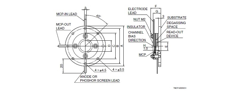
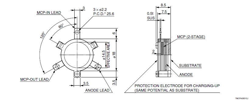
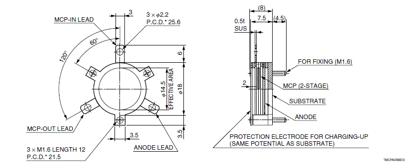
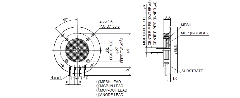
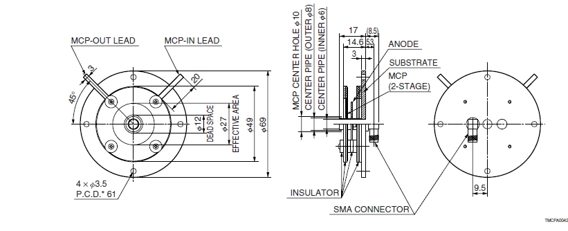
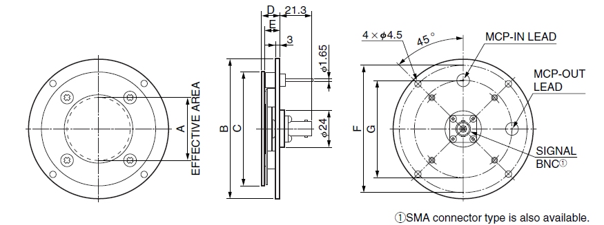
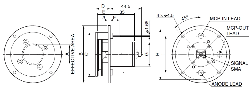
◎ Circular (Demountable)
|
Type No. |
Channel |
Number of MCPs |
Gain |
Puls height |
Dark count |
MCP |
MCP-OUT to anode |
|---|---|---|---|---|---|---|---|
|
F2221 |
12 |
Refer to |
1 stage MCP |
2 stage MCP: 120 |
3 |
1 stage MCP: 1.0 |
Single anode: 0.5 |
|
F2222 |
|||||||
|
F2223 |
|||||||
|
F2224 |
|||||||
|
F2225 |
|||||||
|
F2226 |
25 |
Perform the vacuum baking under 150 °C while keeping the exhaust system at a vacuum pressure below 1.3 × 10⁻⁴ Pa.
|
Anode type |
Number of MCPs |
|---|---|
|
Without readout device |
1 to 3 |
|
Single anode |
|
|
Multianode |
|
|
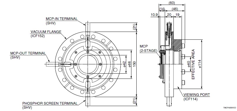
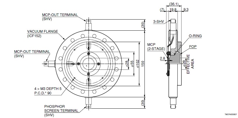
Phosphor screen |
1 to 2 |
|
Symbol |
Description |
F2221 |
F2222 |
F2223 |
F2224 |
F2225 |
F2226 |
Unit |
||
|---|---|---|---|---|---|---|---|---|---|---|
|
A |
Assembly outer size |
φ54 |
φ61 |
φ69 |
φ75 |
φ86 |
φ123 |
mm |
||
|
B |
Mounting screw hole pitch |
φ46 |
φ53 |
φ61 |
φ67 |
φ78 |
φ115 |
mm |
||
|
C |
Insulator outer size |
φ34 |
φ41 |
φ49 |
φ55 |
φ66 |
φ103 |
mm |
||
|
D |
Effective area |
φ14.5 |
φ20 |
φ27 |
φ32 |
φ42 |
φ77 |
mm |
||
|
E |
Effective area of readout device |
φ10 |
φ17 |
φ24 |
φ30 |
φ40 |
φ75 |
mm |
||
|
F |
Maximum height |
15 |
15 |
15 |
15 |
15 |
17 |
mm |
||
|
G |
Distance from bottom of substrate to insulator surface |
No. of MCPs |
1 |
10.9 |
12.9 |
mm |
||||
|
2 |
11.9 |
14.4 |
||||||||
|
3 |
11.9 |
15.9 |
||||||||
|
H |
Distance from bottom of substrate to insulator surface |
No. of MCPs |
1 |
2.8 |
3.8 |
mm |
||||
|
2 |
3.3 |
4.3 |
||||||||
|
3 |
2.9 |
4.8 |
||||||||
Shape may differ depending on product type number.
|
Type No. |
Channel |
Number of MCPs |
Gain |
Puls height |
Dark count |
MCP |
MCP-OUT to anode |
|---|---|---|---|---|---|---|---|
|
F2813 |
15 |
Refer to |
1 stage MCP |
2 stage MCP: 120 |
3 |
1 stage MCP: 1.0 |
Single anode: 0.5 |
|
F2814 |
20 |
||||||
|
F3490 |
12 |
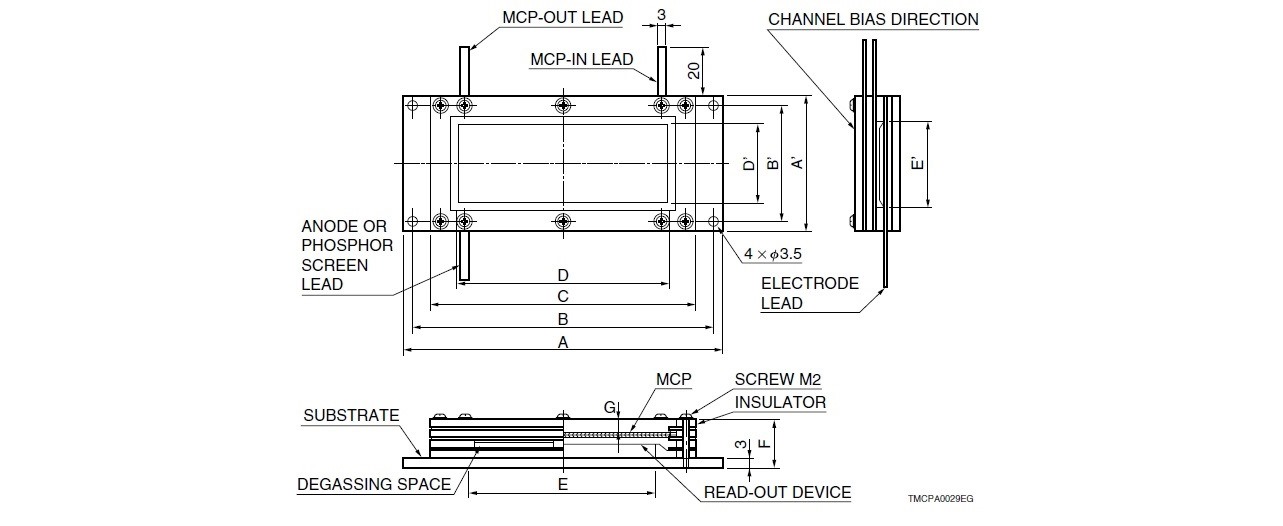
|
Symbol |
Description |
F2813 |
F2814 |
F3490 |
Unit |
||
|---|---|---|---|---|---|---|---|
|
A×A' |
Assembly outer size |
128×54 |
96×76 |
78×29.5 |
mm |
||
|
B×B' |
Mounting screw hole pitch |
120×46 |
86×68 |
72×18 |
mm |
||
|
C×A' |
Insulator outer size |
104×54 |
76×76 |
66×29.5 |
mm |
||
|
D×D' |
Effective area |
81×31 |
53×53 |
55×8 |
mm |
||
|
E×E' |
Effective area of readout device |
80×30 |
50×50 |
52×7 |
mm |
||
|
F |
Distance from bottom of substrate to insulator surface |
No. of MCPs |
1 |
10.9 |
10.9 |
11.9 |
mm |
|
2 |
11.9 |
11.9 |
|||||
|
3 |
11.9 |
12.9 |
|||||
|
G |
Distance from bottom of substrate to insulator surface |
No. of MCPs |
1 |
2.7 |
2.5 |
3.8 |
mm |
|
2 |
3.1 |
2.7 |
3.3 |
||||
|
3 |
2.5 |
2.9 |
2.9 |
||||
|
Anode type |
Number of MCPs |
|---|---|
|
Without readout device |
1 to 3 |
|
Single anode |
|
|
Multianode |
|
|
Phosphor screen |
1 to 2 |
|
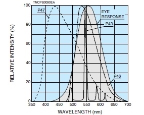
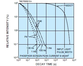
Phosphor screen type |
Peak emission |
Emission color |
Relative energy |
10 % decay time |
Remarks |
|---|---|---|---|---|---|
|
P43 |
545 |
Yellowish green |
1 |
1 ms |
Standard type |
|
P46 |
510 |
Yellowish green |
0.3 |
0.2 µs to 0.4 µs |
Short decay |
|
P47 |
430 |
Purplish blue |
0.3 |
0.11 µs |
Very short decay |
| Spectral emission characteristics | Decay characteristics | |
 |
 |
|
|
③ Decay characteristics after removal
of continuous light input
|
|
Type No. |
Channel |
Number |
Gain |
Pulse height |
Dark count |
MCP supply voltage |
MCP-OUT to anode supply voltage (kV) |
|---|---|---|---|---|---|---|---|
|
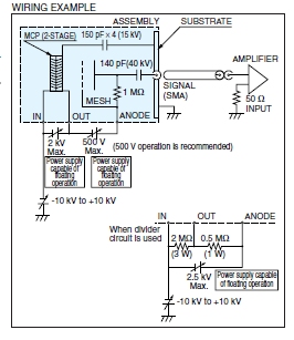
F4655 |
12 |
2 |
5 × 10⁷ |
50 |
3 |
2.5 |
0.5 |
|
F4655-14 |
◎ F4655
Perform the vacuum baking under 150 °C while keeping the exhaust system at a vacuum pressure below 1.3 × 10⁻⁴ Pa.
◎ F4655-14
|
Type No. |
Channel |
Number |
MCP center dead area (mm) |
Gain |
Pulse height |
Dark count |
MCP supply voltage |
MCP-OUT to anode supply voltage (kV) |
|---|---|---|---|---|---|---|---|---|
|
F2223-21SH |
12 |
2 |
8 |
1 × 10⁶ |
— |
3 |
2 |
0.5 |
|
F4294-09 |
12 |
|
Type No. |
Channel |
Number |
Pulse width (FWHM) |
Gain |
Pulse height |
Dark count |
MCP supply voltage |
MCP-OUT to anode supply voltage (kV) |
|---|---|---|---|---|---|---|---|---|
|
F9890-13 |
12 |
2 |
900 |
1 × 10⁶ |
150 |
3 |
2 |
0.5 |
|
F9890-14 |
6 |
|||||||
|
F9890-31 |
12 |
450 |
||||||
|
F9890-32 |
6 |
|||||||
|
F9892-13 |
12 |
1200 |
||||||
|
F9892-14 |
6 |
|||||||
|
F9892-31 |
12 |
700 |
||||||
|
F9892-32 |
6 |
|
 |
|||||||||||||||||||||||||||||||||||||||||
|
 |
|||||||||||||||||||||||||||||||||||||||||||||||||||||||||||||||||||||||||
|
Type No. |
Channel |
Number |
Pulse width (FWHM) |
Gain |
Pulse height |
Dark count |
MCP supply voltage |
MCP-OUT to anode supply voltage (kV) |
|---|---|---|---|---|---|---|---|---|
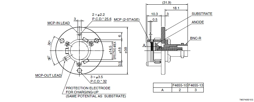
|
F4655-10 |
12 |
2 |
600 |
5 × 10⁷ |
50 |
3 |
2.5 |
0.5 |
|
F4655-11 |
||||||||
|
F4655-13 |
4 |
1 × 10⁶ |
120 |
5 |
2 |
|
Type No. |
Channel |
Number |
Pulse width (FWHM) |
Gain |
Pulse height |
Dark count |
MCP supply voltage |
MCP-OUT to anode supply voltage (kV) |
|---|---|---|---|---|---|---|---|---|
|
F12334-11 |
12 |
2 |
1.5 |
1 × 10⁶ |
— |
3 |
— |
0.5 |
|
F12395-11 |
||||||||
|
F12396-11 |
◎ F12334-11, F12395-11, F12396-11
|
Type No. |
Channel |
Number |
Gain |
Pulse height |
Dark count |
MCP supply voltage |
MCP-OUT to anode supply voltage (kV) |
|---|---|---|---|---|---|---|---|
|
F2225-21PGF |
12 |
2 |
1 × 10⁶ |
— |
3 |
2 |
4 |
|
F6959 |
3 |
檔案下載